DC Vibration Motor Introduction
Posted in 2018-06-02 10:41:23 in Tech Blog, 2 Comments
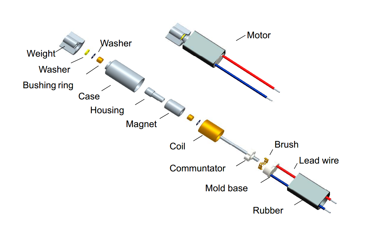
A brushed DC Vibraiton motor is an electromechanical engine driven by a DC power supply. The basic parts of a brushed DC vibration motor are:
Case, bearing and stator magnets (stator, i.e. stationary),Electric motor shaft and ashers,Armature / rotor,Commutator (and sometimes a Varistor), and Brushes and terminals or leads.
The picture below shows this layout in an exploded view of a typical DC motor – in cases like this a small Ø4mm DC vibration motor.
The Principle Of DC Vibration Motor Structure
The Armature is mounted on the shaft and has windings terminated to a commutator (sometimes with a varistor to reduce electromagnetic interference from commutator sparking); motor terminals (or prospects) are connected to the engine windings through through the electric motor brushes.
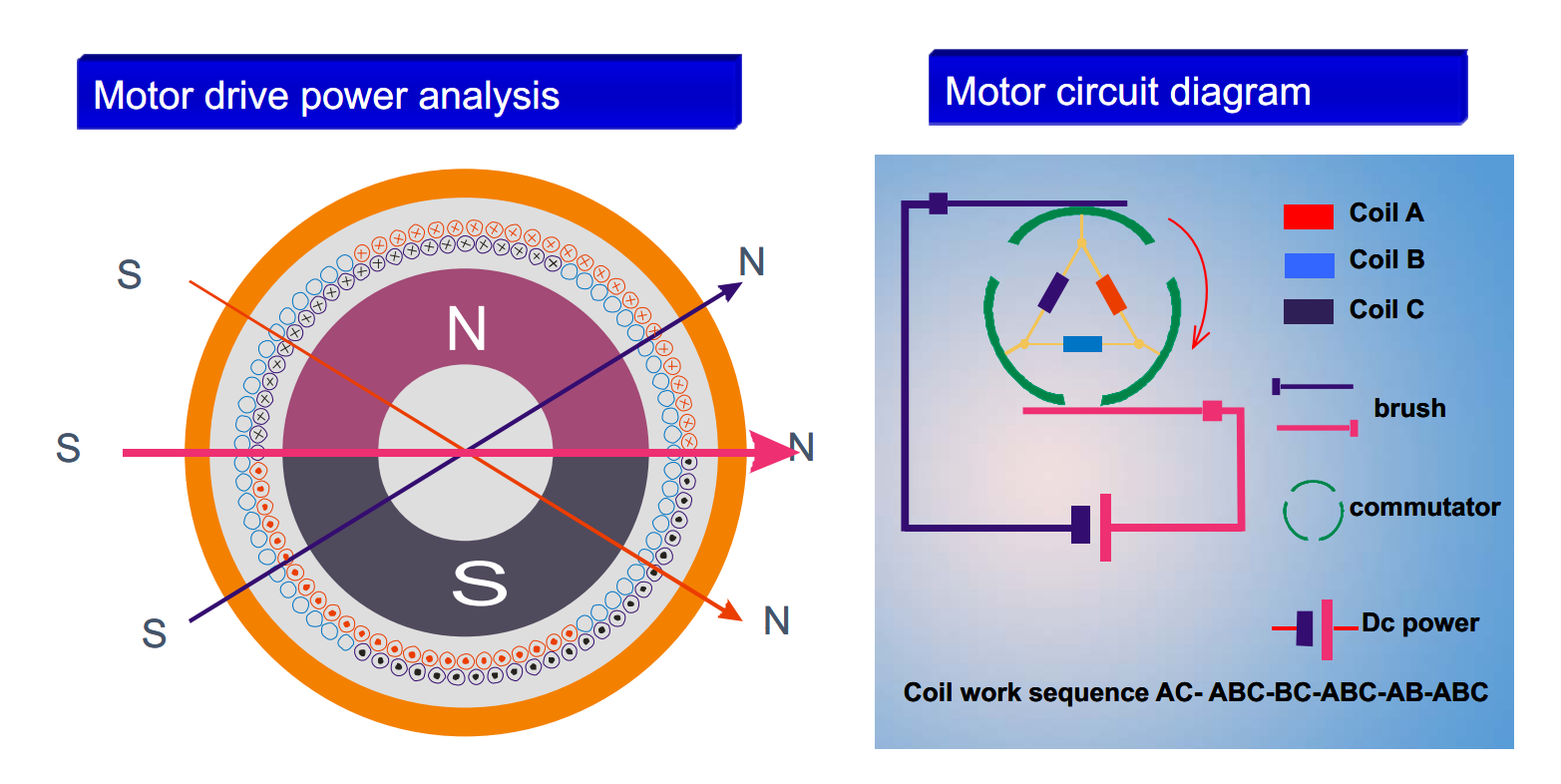
The stator magnets will have at least two permanent magnet poles. The electromechanical motor is designed such that opposite magnetic fields of the energized windings and the stator magnets causing the shaft to rotate. When the armature is certainly aligned with the stator magnets, the brushes, which are also fixed to the engine case, will connect to the next commutator segment and thereby energize another winding. This will change the magnetic field the armature, which causes the motor to continue rotating. The diagram below shows the stator, armature and commutator geometry in more detail.
Armature, Stator and Commutator Geometry on a 3-pole DC MotorArmature, Stator and Commutator Geometry on a 3-pole DC Motor
Two-pole brushed motors have two big problems. The first is that when the rotor poles and the stator poles are in line the torque is zero and the electric motor cannot start from this position. The other problem is that during the motor revolution, there is a moment where the brushes touch both the commutator sections; this qualified prospects to a short circuit of the inputs, condition that can damage the power supply and reduce performance.
For this reason, most small electromechanical DC motors have a minimum of three poles. The rotor provides three windings that are wired in a triangle (delta) configuration to the three sections of the commutator. The brushes touching two opposing sides of the commutator and, depending on the rotor angle, will energize the three coils in turn. The wiring and the position of the windings are created to always create a power moving the rotor in a particular direction given a constant brush polarity.
There are two main types of construction for small brushed DC motors: coreless and iron core. The use of an iron core rotor is very common for motors above 10mm of diameter. The coils are winded on a laminated iron primary; this gives them a rigid support and helps to dissipate heat. Drawbacks are the inertia generated from the iron core mass, and the high coil inductance that limit brushes and commutator lifestyle.
Motors of diameter 10mm or smaller are usually realized using a coreless building – an exploded diagram of this structure is detailed below. In cases like this the windings by themselves create the rotor structure. The rotor is usually hollow and the stator magnet can be placed in the centre, saving space, reducing the inductance and increasing the heat dissipation (since the windings are closer to the case / outside of the motor.
Considering Baolong Company?
Email us at:
sales@baolong.com
Or call us at:
+86 (0577) 62572888